
BIO340 Laboratory Guide #6
EXCITATION AND CONTRACTION OF
FROG SKELETAL MUSCLE
Vertebrate skeletal muscles are made of a number of motor units, each of which consists of a single motor neuron and the individual muscle fibers (cells) it innervates. When a motor neuron is depolarized to threshold, it generates an action potential, and all of the muscle fibers in its motor unit contract simultaneously. This contraction causes the muscle to twitch. Because the muscle fibers in a motor unit are arranged in parallel, the tension developed during the twitch is proportional to the number of muscle fibers in the unit. Because the motor axons in a nerve have varying thresholds, gradually increasing the intensity of an electrical stimulus applied to the nerve will gradually increase the number of activated motor units, with a corresponding increase in tension. This process is often referred to as recruitment or spatial summation. At a stimulus intensity that is above threshold for all of the motor axons, the twitch tension of the muscle will be maximal.
Muscles can produce tensions that are much larger than the maximal twitch tension, however. Repeating the stimulus pulse at low frequency produces a train of muscle twitches. An important feature of skeletal muscle (but not cardiac muscle, fortunately) is that the muscle twitch is longer in duration than combined length of the muscle action potential and its refractory period. As a consequence, if the frequency of nerve stimulation is gradually increased, successive muscle contractions will begin to overlap in a process called temporal summation. The resulting tension will exceed that developed during a single twitch. At a critically high frequency of stimulation, a sustained contraction called tetanus is produced.
In this laboratory exercise, several of the contractile properties of skeletal muscle will be investigated in the gastrocnemius (calf) muscle of the frog. This muscle is innervated by the tibial nerve, one of the two main branches of the sciatic nerve. We will study muscle excitability and contractility in an isolated preparation of the frog sciatic nerve and gastrocnemius muscle. We will be doing this under approximately isotonic (constant tension or load) conditions, rather that under the isometric (constant length) conditions, which you studied in BIO112.
Additional Reading:
Chapter 10, especially pages 362-370, 375-378, 392-392 in Eckert Animal Physiology (5th Ed.) by Randall, Burggren, and French.
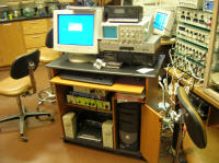
I. EQUIPMENT SETUP
We will be using the electronic stimulator to initiate muscle contractions by delivering pulses through a pair of silver wire electrodes mounted in a probe. Contractions of the muscle will be conveyed via a thread to the central rod of a linear displacement transducer. This transducer converts changes in muscle length to changes in electrical resistance. A bridge amplifier converts theses resistance changes to voltage changes. The output cable of the bridge amplifier carries this voltage signal to a PowerLab input. Suspending a fixed weight to the transducer rod allows for isotonic muscle contraction under a fixed load.
The electronic equipment needed for this experiment includes a displacement transducer, an ETH-400 transducer bridge, an electronic stimulator, a stimulator probe with silver wire electrodes, and a PowerLab/PC station.
To save time in this lab you should split your group into two subgroups, one of which will begin perform the dissection (Section II) while the other sets up the equipment as described below.
Equipment Setup Procedure:
1) Clamp the body of the displacement transducer about halfway up a ring stand. The "hat" should be on top. Connect the transducer cable to Channel 1 of the ETH-400 bridge amplifier. Connect the Channel 1 output of the ETH-400 to the + CH 1 input jack of the PowerLab box, using a BNC cable. Make sure that the bridge power cable is plugged in and that the red light on the bridge is on.
2) Mount the femur clamp about 3/4 of the way up the same ring stand. Mount the stimulator probe just above the femur clamp. Carefully plug the stimulating electrodes into the stimulator probe. Attach the probe leads to the electronic stimulator outputs, red-to-red and black-to-black via the adapter cable. Use a double-banana to BNC cable to also connect the stimulator cable to the + CH 2 input on the PowerLab, so that you can monitor the stimulator output directly.
3) Connect a BNC cable from the + Output jack of the PowerLab to the SYNC TRIGGER IN jack of the stimulator (near the lower left of the front panel). This cable will allow the internal PowerLab stimulator to trigger the SD9 electronic stimulator.
4) Check out all of the cable connections with the instructor before proceeding.
5) Make sure that the stimulator MODE is set to OFF. Turn on the stimulator, turn on the PowerLab box, boot the PC, and launch Scope.
6) Set Input A to Ch1 and Input B to Ch2. Adjust the display area so that most of the vertical space is occupied by Input A. Set Samples:2560 and Time:500 msec in the submenu at the bottom of the Speed menu.
7) Under the Display. . . menu chose Overlay Stimulator and set it to display the PowerLab stimulator trace at the top of the display.
8) Under the Setup:Sampling menu set Mode:Single and Source:User. Under the Setup:Stimulator menu set Mode:Pulse, Delay to 100 msec, Duration to 5.0 msec, and Amplitude to ~4 volts.
9) Use the Input A Input Amplifier... to set the display range to 1 V and activate the Positive input and the Invert. Use the Input B Input Amplifier... to set the display range to 10 V and again activate only the Positive input.
10) Use the Units Conversion... option on Channel 1 to have Scope convert directly from mV to mm muscle contraction so that the vertical axis reads in mm, rather than mV. The conversion ratio is 1.2V to 1.0cm. (see the instructor for help, if necessary).
11) Double check the setup of all of your equipment, and make sure that you know the locations and functions of all of the controls. Refer to the instrumentation tutorial or consult the instructor if you have any questions.
II. DISSECTION AND MOUNTING OF THE NERVE/MUSCLE PREPARATION
As in the previous experiment, try to work quickly and carefully. Wear gloves. Read all the way through the dissection procedure before you start. Handle both the nerve and the muscle carefully, and touch them only with the glass rod and hook. If you stretch the muscle, you will reduce its contractility, so try not to stretch it during the dissection. Don't let the muscle or nerve touch the outside of the frog's skin. Keep all exposed tissue moist with frog Ringer's.
Dissection Procedure:
1) Put on a pair of gloves. Obtain yet another decapitated frog from your instructor or one of the other groups. Try not to ruminate on the fact that amphibians are in a serious decline worldwide. Cut off a hind leg at the upper end of the thigh and, if there is still one leg left, give the rest of the frog to one of the other laboratory groups.
2) Remove the skin completely from the leg. Try not to let the outside of the skin touch the muscle of the leg. Wash your hands and change your gloves.
3) Expose the sciatic nerve in the thigh, free it between the knee and the hip, and tie a thread around it as close as possible to the hip. If you have correctly identified the sciatic nerve the leg muscles should twitch violently when you tighten the knot on the tread. Sever the nerve proximal (towards the body of the frog) to the tie, then lay the nerve along the gastrocnemius muscle. Wet the nerve and muscle with a few drops of Ringer's solution. Be sure not to touch the nerve with your fingers or with any metal instruments, only with the thread and the glass hooks.
4) Carefully cut away the thigh muscles (but not the nerve!) leaving the femur (thigh bone) exposed. Use a needle to poke a hole in the Achilles tendon at the heel. Tie a thread through the hole in the tendon, then use a sharp scalpel or scissors to separate the tendon from the ankle distal to the thread.
5) Gently lift the gastrocnemius and sciatic nerve with a glass rod, while cutting through the tibiofibula (lower leg bone) and the other lower leg muscles. Make your cut below and close to the knee. You will end up with the gastrocnemius muscle attached to the femur at one end and the thread at the other end, with the muscle's nerve supply intact.
6) Place the shaft of the femur between the jaws of the femur clamp and tighten the jaws securely. Allow the nerve to hang along the muscle for now, and moisten both with Ringer's. Do not let the nerve touch the femur clamp or the ring stand. Tie the Achilles tendon thread to the upper end of the transducer rod, just above the plastic "cap". The ~6 gram weight of the transducer rod will function to keep a slight tension on the muscle.
7) Now carefully adjust the position of the clamp, transducer, and/or bridge offset knob until the muscle is perpendicular to the femur, the transducer rod is vertical, the thread is vertical, and Input A reads 0 volts. Using the running Input Amplifier... window for Input A will help you with this last determination.
8) Position the silver stimulating electrodes on the probe tip as close to the knee joint as possible. Gently wrap the nerve around the stimulating electrodes and moisten it with Ringer's solution.
9) At this point you should ask the instructor to come over and do a quick stimulation check to make sure that your nerve/muscle preparation is viable and responsive. Once you have confirmed this, rewet the nerve with Ringers, then coat all of the exposed nerve with a layer of Vaseline to keep it from drying out.
Be sure that the muscle and exposed sciatic nerve are kept moist with Ringer's solution. DO NOT ALLOW RINGER'S SOLUTION TO COME IN CONTACT WITH ANY OF THE RECORDING EQUIPMENT, INCLUDING THE TRANSDUCER. Don't allow Ringer's solution to accumulate on the transducer cap. The viability of the preparation is limited and it will begin to deteriorate as soon as the animal is sacrificed. Therefore, it is important to avoid unnecessary stimulation of the muscle and to be efficient in your use of time. If the muscle gets "twitchy" and starts contracting on its own, your best bet is to make sure that the nerve is not being stretched, wet down both the nerve and muscle with Ringer's solution, and simply wait for the preparation to "calm down".
III. RECORDING FROM THE NERVE/MUSCLE PREPARATION
Skeletal muscle contraction is generally studied under one of two experimentally imposed conditions: isometric (constant length) or isotonic (constant load). We will be studying the gastrocnemius muscle under isotonic conditions, where the muscle contraction moves the transducer lever, lifting a set weight. Under these circumstances, the muscle does external work by displacing the weight. The degree of shortening of the entire muscle (contraction) is reflected by the degree of displacement of the transducer rod.
As you work through the following procedures, be sure to save important Scope and Chart records to disk. Keep track of your chart records by making Comments. Save your file periodically. Rename your file periodically using the Save As... option, so that older versions of your file are maintained (so if you mess up you don't lose all of your data). When you are instructed to print out a Scope or Chart record, do that after the experiment, while you are preparing your data sheet. Use your time during the experiment to collect the data, making sure you have obtained and saved the records you will need for the print-outs and measurements you will make later.
Again, keep the preparation moistened with Ringer's.
A. Components of the Muscle Twitch:
1) Using a stimulus duration of 0.1 to 0.5 msec. and an electronic stimulator delay of ~0 msec, deliver pulses of gradually increasing voltage by repeatedly triggering Scope sweeps, while you watch the muscle and the Scope trace. When you reach a stimulus voltage that elicits a visible twitch, you may want to clear out the earlier traces, using New under the File menu.
2) Continue to increase the voltage until a maximal twitch is produced. Be sure to use Page Comments liberally to label each section of the record with the stimulus parameters.
3) Now look back through the records of the twitches that were produced as you increased the stimulus voltage. Pick out a record for which the twitch is roughly one-half-maximal, and one where it is roughly one-tenth-maximal. Stimulate the muscle again if you need to get a closer approximation to either of these response amplitudes.
Q1: Explain any differences in these parameters for the three twitches.
Q2: What are the events that contribute to the latent period, and approximately how long does each event last? (To answer this question, you may have to refer to your textbook and the results of the sciatic nerve lab.)
B. Work Performed by the After-Loaded and Free-Loaded Muscle
1) Hang the 5 gram mass-holder on the 6g transducer rod. Readjust the ETH-400 bridge so that the lever is again horizontal, the muscle is taut with the 11 gram load of the transducer rod and the, and the Scope trace reads 0 Volts (or 0 mm). Move in a stabilizing support for the transducer rod, so that it prevents the rod from being pulled down past this neutral position. In this situation the support bears all of the weight that is added to the lever. The muscle, which is said to be "after-loaded" will not "feel" the weight until it begins to contract.
2) Set the Display to Show Overlay. Using a stimulus level that produce maximal twitches, trigger a single sweep. Be sure to annotate the Scope page with "11 grams".
3) Keep the stimulation settings constant for the rest of this section. Now add masses to holder in 5 gram increments, triggering a single sweep after each addition. Annotate each Scope page with the corresponding weight (e.g. "16 grams","21 grams", etc.). Stop adding masses when the muscle no longer twitches. Save the set of annotated twitches.
4) At a later time, measure the length of contraction and the duration of the latent period for each load. Record your measurements as Table 1. Remember that the initial weight corresponding to the transducer rod and hanger, is 1 grams. For each mass, calculate the work performed by the muscle as it shortens and add these results to Table 1. Use the formula Work = F x D, where F = force and D = length of shortening in cm. Force in dynes can be calculated as the mass in grams x the acceleration of gravity (980 cm/sec2).
5) Now, unload the masses back to the initial 11 grams of the transducer rod and empty hanger. Move the support away from the transducer. Under these conditions, the muscle is said to be "free-loaded", and will be stretched by the load before it begins to contract.
6) Repeat the procedure above in steps 2-3, adding weights in 5g increments. Because the muscle is being stretched by the weight, you will have to rezero the bridge before triggering each sweep and twitch. Unload and remove the weight holder as soon as you are done with your recording.
7) At a later time, measure the length of contraction and the duration of the latent period for each load. Create a new Table 2 for this free-loaded condition. Remember that the initial weight corresponding to the transducer rod and hanger, is 11 grams. For each mass, calculate the work performed by the muscle as it shortens and add these results to Tables 1 and 2. Use the formula Work = F x D, where F = force and D = length of shortening in cm. Force in dynes can be calculated as the mass in grams x the acceleration of gravity (980 cm/sec2).
Q3: Under which condition could the muscle lift more weight? Why does this make physiological sense (in a live frog is the muscle after-loaded or partially free-loaded)? What is the histological (actin & myosin configuration) explanation for this?
Q4: Discuss the basis for differences in the latent period, length of contraction, and work performed under the after-loaded and free-loaded conditions.
Q5: Do your results support the notion that live frogs can actually jump? In other words, do your maximal work values correspond to a significant fraction of the work involved in moving � frog � meter during a jump (recall that an intact frog has other leg muscles, and a whole other leg to help)?
C. Temporal Summation of Contractions
For this experiment it will be easier to use the Chart application for a continuous recording.
1) Make sure that you have saved all the Scope data that you will need, then close Scope and open Chart.
2) Turn off all of the channels except and 1 and 2. Adjust the display so that Channel 1 occupies 2/3 of the space and Channel 2 occupies the remaining third. Set the recording speed to 100/s. Set the vertical to about twice what you were using for the earlier Scope recordings. Again, use the Units Conversion... option on Channel 1 to have Chart convert directly from mV to mm muscle contraction so that the vertical axis reads in mm, rather than mV. The conversion ratio is 1.2V to 1.0cm. (see the instructor for help, if necessary).
3) Unplug the stimulator trigger from the PowerLab output. Set the stimulator frequency to 0.5 Hz.
4) Start the Chart display and choose a stimulus intensity that produces a maximal twitch to single stimulator pulses.
5) Now set the stimulator MODE to REPEAT and look for the effect of stimulation frequency on temporal summation of twitches. The best way to do this is to run Chart for about 5 seconds, quickly double the stimulus frequency, run chart for 5 more seconds, double the frequency again, etc. Increase the stimulus frequency until a tetanic contraction is produced. Don't stimulate at the tetanic rate for more than 10-20 seconds, maximum. Drop the stimulus frequency back to a low level and stop the Chart record.
You won't be able to label the chart as you go, but by doubling the stimulus frequency in discrete steps you should be able to come back to your record and label it at the end of the recording run. It is a good idea to insert some labels indicating stimulation frequency into the record immediately after you finish.
Q6: Explain the mechanism underlying summation of contractions and tetanus. What is happening in each case at the level of the individual sarcomere?
Q7: Explain why the length of contraction varies with stimulus frequency. Again, carry this explanation to the level of the individual sarcomere.
D. Shutting Down
1) Make sure that you have saved all of your data to the hard drive, then quit Scope. Turn off both the PowerLab box and the stimulator. Disconnect the cables from the stimulator, the PowerLab, and the axon circuit board.
2) Remove the nerve and muscle and properly dispose of them.
3) Carefully wipe off the transducer.
4) Rinse off the bone clamp and stimulating probe with distilled water, and set aside to dry.
5) return all unused solutions to the refrigerator.
IV. PREPARATION OF THE LAB DATA SHEET
Your data sheet should include all SIX of the items described in the boxes above. Make sure that the axes of all of the graphs and print-outs are labeled and calibrated. You should certainly discuss your results and the answers to the questions with your partners and others in the lab. However, please work independently when you prepare your data sheet.