
BIO325 Laboratory Guide #5 (2024)
Electrophysiology III:
RESISTORS, CAPACITORS, AND RC CIRCUITS
Simple electronic circuits have two central applications in neuroscience. The first is in understanding and modeling the electrical properties of neural membranes and neural excitability. The second is in designing electronic equipment to record from nerve cells. These applications require some understanding of the behavior of two electronic components, the resistor and the capacitor.
This lab uses the Resistor/Capacitor Test Model (RCTM) circuit board, a multimeter, a simple 9 volt battery, alligator test leads, and the MacLab/PowerLab recording system.
I. RESISTORS AND RESISTOR CIRCUITS
First some definitions.
Electrical charge is indicated by the symbol Q and is measured in units called coulombs. One coulomb is approximately 6.24 x 10¹⁸ units of charge (electron equivalents). Current is the rate of movement of charge past a given reference point, is indicated by the symbol I, and is measured in units called amperes, or just amps (A). One amp = one coulomb per second (I = dQ/dt). Voltage is a measure of electromotive potential between two points, essentially how hard a current is being pushed. Voltage is indicated by the symbols V (for measurable potentials) and E (for theoretical potentials) and is measured in units called volts (V). Resistance opposes the flow of electrical current. Resistance is indicated by the symbol R and is measured in units called ohms (). Impedance is indicated by the symbol Z and is closely related to resistance. The terms resistance and impedance will be used interchangeably in this class. Conductance, indicated by the symbol g and measured in units called siemens (S), is the inverse of resistance (g = 1/R). The relationship between current, voltage, and resistance is expressed by Ohm's Law (V = IR). In neuroscience it is often more convenient to express Ohm's Law in terms of conductance (I = gV) and to think of conductance as the ratio between voltage and current (g = I/V), that is the ratio between how rapidly charge flows and how hard it is being pushed.
In the first part of this exercise you will learn how resistors behave, how to calculate equivalent resistances in circuits, and how to build a voltage divider.
A. Using the RCTM Board
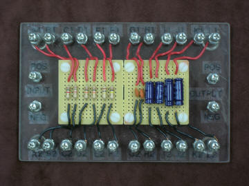
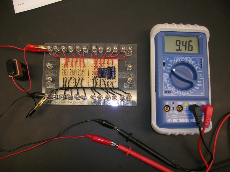
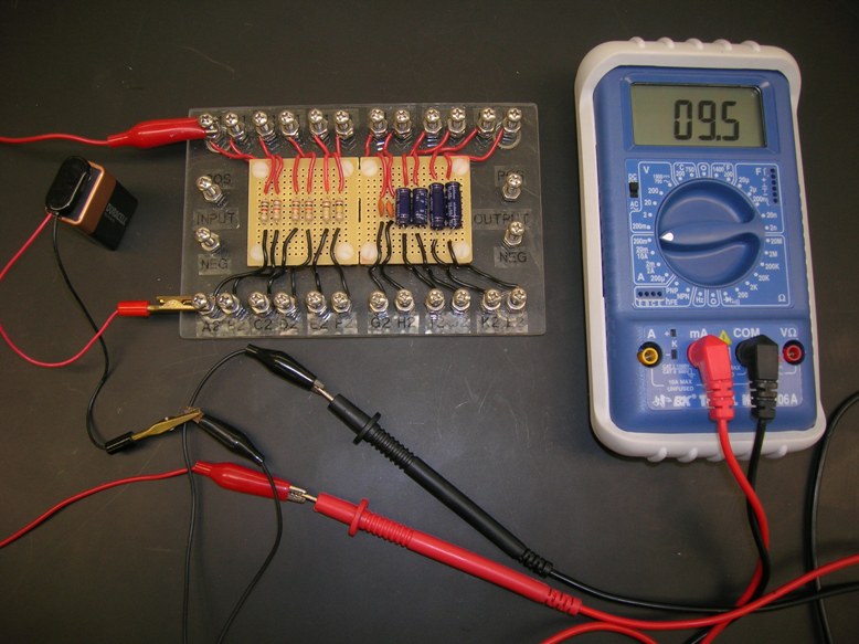
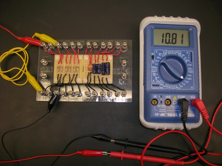
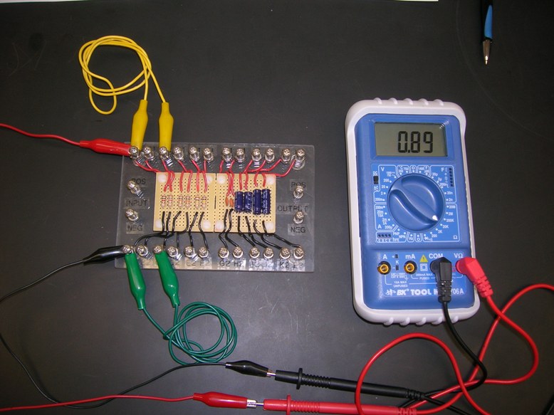
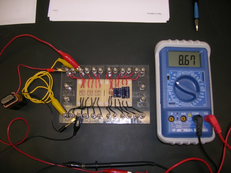
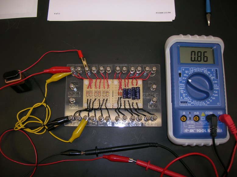
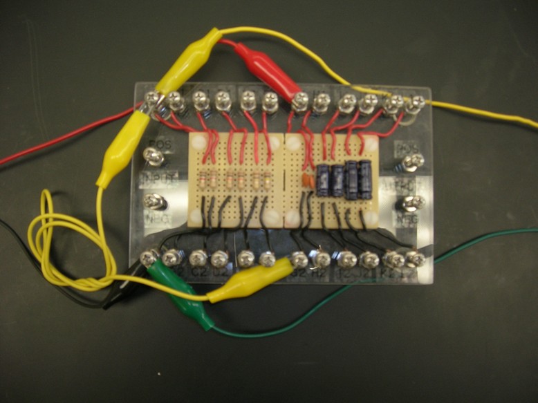
1) To start with, clear a space in the center of your recording cage and set the RCTM board (pictured in the link at the right) in this area. Locate the labeled screw posts (A1-L1, A2-L2). The A-F posts are connected to three different values of resistor, while the G-L posts care connected to three different values of capacitor. There are two additional screw posts at either end which can be used as neutral, unconnected points.
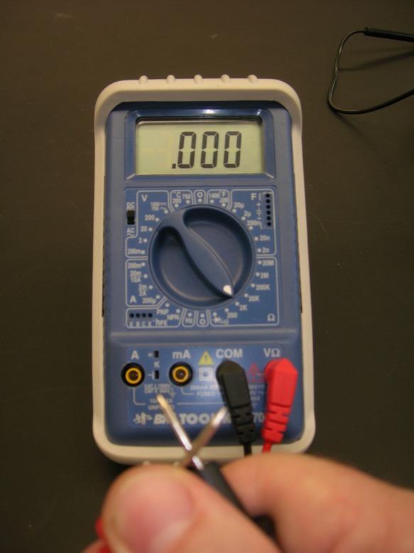
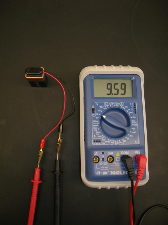
2) Locate the digital and/or analog multimeter. The instructor will walk you through the use of this device.
3) Attach the connector cap to the 9V battery. Make sure that the the two wire leads coming off of the cap do not directly touch each other and do not directly touch any other conductive metal surfaces, as this will cause the battery to become very hot as it rapidly drains its charge.
4) Locate your set of colored alligator clip leads.
5) All set and ready to go.
B. Voltage, Current, and Resistance - Confirming Ohm's Law
1) Set the multimeter to measure resistance on the 1K or 2Kohm scale. Plug the test leads into the multimeter - black to -COM and red to V--A. If you are using an analog multimeter, hold the tips of the multimeter leads together and adjust the OHMS ADJ knob to zero the needle to 0 ohms on the green scale (right extreme).
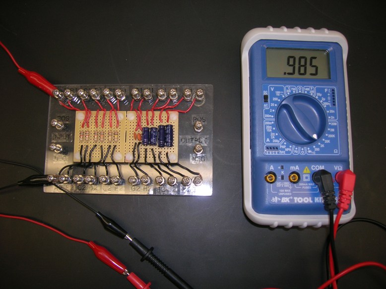
2) Use alligator jumper cables to attach the red test lead of the multimeter to point A1 and the black test lead to point A2 on the RCTM board. This A resistor is nominally 1.0 Kohm (+ 5%). What is its actual (measured) resistance? RA = . What are the measured resistances of the other five resistors B, C, D, E, and F? You will have to adjust the scale knob on the multimeter for some of these.
3) Disconnect the multimeter leads. Switch the multimeter to the 20V range. Now connect the terminals of a 9 volt battery to the multimeter leads - red (+) to red and black (-) to black. What actual voltage do you read for this battery (read the lowest of the four DC scales on an analog meter)? V =
4) Connect both the red battery and red multimeter leads to A1 and both black leads to A2. In this circuit the entire voltage "drop" is across the resistor RA. Is the measured voltage the same as when there was no resistor connecting the red and black leads? What will the measured voltage be if you substitute resistor B, C, D, E, or F? Test your guess.
5) Disconnect all four leads. Switch the multimeter to the 50 or 200 mA scale. Now connect the red multimeter lead to A1, the red battery lead to A2, and the black battery and black multimeter leads to each other. What is the measured current in this circuit (read the black DC scale third from the top on the analog multimeter)? IA = . What are the measured currents if you substitute the other resistors B, C, D, E, and F? To measure E and F you will have to use the analog multimeter.
6) Disconnect all leads and switch the multimeter to OFF.
Q1: Does VA = IA RA? Does this relationship hold for the other resistors B, C, D, E, and F?
C. Equivalent Resistances
1) When two resistors are placed in series, as in the diagram below, then current flowing through this path must flow through both resistances. The total (T) resistance for this path is simply the sum of the two resistances (RT = R1 + R2). Confirm this relationship by using an alligator jumper to connect the A (1 Kohm) and C (10 Kohm) resistors in series, then measuring the total resistance using the multimeter set to the 10 Kohm scale.
RA = RC = RT =
2) When two resistors are placed in parallel, as in the diagram below, then current flowing through this circuit is split between the two paths. In this case the total (T) conductances sum (gT = g1 + g2). Since g = 1/R, then (1/RT = 1/R1 + 1/R2). Solving for RT gives
RT = (R1R2)/(R1 + R2). Confirm this relationship by using alligator jumpers to connect the A (1 Kohm) and C (10 Kohm) resistors in parallel, then measuring the total resistance using the multimeter set to the 10Kohm scale. Remember to rezero the multimeter using the OHMS ADJ knob each time you change the scale, if you are using an analog meter.
RA = RC = RT =
3) Repeat your measurements using at least one other combination of resistors, wired first in series, then in parallel.
Q2: How well do your calculated and measured equivalent resistance values for RT agree for resistors in series? in parallel?
D. Series Voltage Drops
1) Kirchoff's Current Laws state that current always flows in a complete circle and that the current flowing into any point in a circuit must equal the current flowing out of that point. When two resistors are placed in series, according to Kirchoff's Current Laws, the same current flows through both resistors (IT = I1 = I2). The relationship expressed in Ohm's Law (V = IR or I = V/R) implies that the voltage drop across each resistor is proportional to its resistance (V1/R1 = V2/R2, or V1/V2 = R1/R2).
2) Verify this relationship by connecting the A and C resistors in series, applying the output of your 9V battery across both resistors, then using the multimeter to measure the voltage across each resistor.
RA = VA =
RC = VC =
RA /RC = VA /VC =
Q3: Do your results support Kirchoff's Current Laws? I.e. how well do your resistance ratio and voltage ratio agree?
E. Voltage Divider Circuit
1) A series resistance circuit where an output voltage is measured across the second resistor is called a voltage divider. In this circuit the ratio between the input and output voltages is determined by the relative sizes of the input (first) and output (second) resistors. Specifically Vout/ Vin = Rout/( Rout + Rin) or Vout = Vin Rout/( Rout + Rin). This circuit is very useful for reducing or "stepping down" the size of a signal, for example if you don't want a large signal to overdrive the inputs of a sensitive amplifier or if you don't want your amplifier to draw much current off of whatever you are recording from. To do this you would use a circuit where Rin is large relative to Rout.
2) Connect the A and C resistors to form a voltage divider circuit as in the diagram below, where Vin represents the 9V battery and Vout is measured on the multimeter. Notice that, although the diagram may look different, it is actually the same as the first setup in part C1 above, but with the order of the resistors reversed.
Q3: Can you confirm that Vout = Vin RA/( RA + RC)?
Q4: If you were to substitute RE for Rc would the recorded voltage across RA get bigger or smaller? Why? Check your answer/guess with the multimeter after modifying your circuit appropriately.
II. Capacitors, Membrane Equivalent Circuits, and RC Filters
Capacitance is a somewhat trickier concept than is resistance. Capacitors store charge, generally on conductive plates separated by insulating spaces. Capacitance may be understood as the ability to store or spatially separate charge. Capacitance is represented by the symbol C and is measured in units called farads (F). Formally, capacitance is defined by the relationship C = Q/V. In other words, capacitance is the ratio between the charge across a capacitor and the voltage required to separate that charge.
A more useful mathematical relationship for neuroscientists is the current IC through a capacitor, specifically IC = C dV/dt. The derivation of this formula is: C = Q/V, so Q = CV and dQ/dt = C dV/dt, and since I = dQ/dt, then IC = C dV/dt. Notice that in these equations we have treated capacitance C as a constant, rather than a variable.
So how does a capacitor behave in an electrical circuit? As a voltage is first applied across a capacitor, charge initially flows freely onto its conductive plates and the capacitor behaves as if it has zero resistance. However, as charge accumulates, the capacitor resists the flow of additional charge (because like charges repel) and the apparent resistance rises. When the capacitor is "charged" to its capacity, no more capacitive current can flow and the capacitor behaves as if it has infinite resistance. Charging of a capacitor and the consequent drop in capacitive current follow complementary exponential curves. How rapidly a capacitor charges and blocks current flow is directly related to the voltage applied and inversely related to the size of the capacitor - its capacitance.
In this exercise you will "input" a short, square-wave current or voltage pulse across several simple circuits and record the resulting amplitude and time course of the resulting voltage �output". The first two of these circuits correctly model some limited aspects of a nerve cell membrane, and therefore are simple "membrane equivalent circuit models". The final two circuits illustrate another important application of resistor-capacitor (RC) circuits, namely as frequency-selective filters for reducing unwanted electronic noise from recordings.
A. Membrane Equivalent Circuits
1) Startup the PC, turn on the PowerLab box, and launch the Scope application.
2) Set up the Scope software for triggering stimuli and recording responses as follows. Set Input A to Channel 1 and Input B to Channel 2. Under Input A open the Input Amplifier dialog box, select Single-ended (unipolar recording), turn all filters off, and set the Range to 2V. Repeat this process for Input B, setting the Range to 200mV. In the Time Base box set Time: to 50 msec and Samples: to 2560. Under the Setup menu choose Sampling . . ., then set Mode: to Single and Source: to User. Under the Setup menu select Stimulator . . ., then set the stimulator Mode: to Pulse, Delay to 0, Duration 1 msec and Amplitude to about 4 Volts. Finally, under the Display menu select Display Settings . . ., then set the Graticule to a grid pattern and Channels A and B to attractive colors.
3) You will be using the PowerLab stimulator only to trigger the Grass electronic stimulator. To do this, simply connect the Output + of the PowerLab box to the TRIGGER IN of the Grass electronic stimulator with a BNC cable. Any subsequent changes in stimulation settings should be made ONLY on the electronic stimulator and NOT on the PowerLab stimulator.
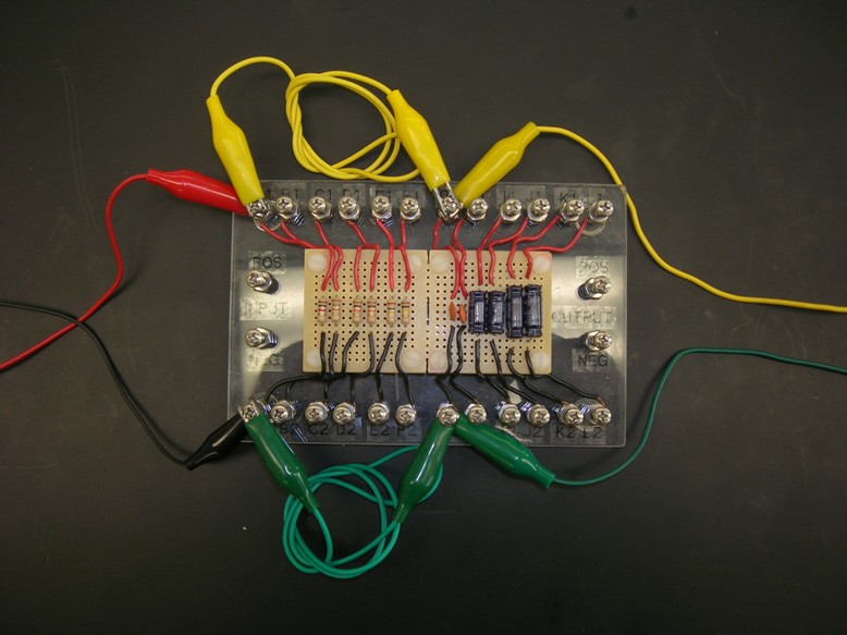
4) Make sure that the Analog Stimulus Isolator (constant-current unit - CCU) box is NOT plugged into its power supply. Connect the electronic stimulator through the CCU as follows. Connect the special output cable to the output jacks of the electronic stimulator, then plug the free double banana plug end of this cable into a double banana-to-BNC adapter. Pay attention to correct plug polarity � the tab (negative) side of the plug goes into the black side of the jack. Plug the male BNC plug of this adapter into the SIGNAL IN on the CCU. Attach a red alligator jumper lead into the positive (red) output jack of the CCU. Attach a black alligator jumper lead into the negative (black) output jack of the CCU. MAKE VERY SURE THAT THE FREE ENDS OF THESE TWO OUTPUT LEADS DO NOT TOUCH, ESPECIALLY WHEN A STIMULUS PULSE IS BEING DELIVERED!!
5) To set up the recording input cables for the PowerLab box, do the following. Connect a BNC-to-red double banana cable to cable leading to the the CH1+ input of the PowerLab box. Plug the free end of this cable into the stimulator output cable, where it connects to the CCU input. Make very sure that the polarity on these two double banana plugs matches � i.e. that the tabs on the plugs line up. Now connect a BNC-to-black double banana cable into cable leading to the CH2+ input of the PowerLab box. Attach a yellow alligator test clip lead to the positive (nontab) banana plug at the free end of this CH2+ cable. Attach a green alligator test clip lead to the negative (tab) banana plug at the free end of this CH2+ cable
6) CHECK YOUR WIRING AND POWERLAB SETTINGS WITH THE INSTRUCTOR BEFORE PROCEEDING.
7) Make sure that the Grass stimulator MODE is set to OFF, then turn on the stimulator. Set the stimulator DELAY to 10 ms, the DURATION to 20 ms, and the VOLTS to 1.0 Volts. Set the STIMULUS to REGULAR, and the POLARITY to NORMAL and the OUTPUT to MONO(POLAR).
8) Set up the CCU as follows. Set the CCU POLARITY to Bipolar and the RANGE to .1mA/V. Turn on the CCU. The ERROR light should flash briefly; if it remains on, immediately turn off the CCU and consult with the instructor.
9) Attach both the CCU+ output (red alligator clip) and PowerLab CH2+ input (yellow alligator clip) to point A1. Attach both the CCU - output (black alligator clip) and PowerLab Ch2 reference input (green alligator clip) to point A2. Your circuit should match the diagram below, where Iin is the input pulse to be supplied by the CCU and Vout is the output pulse to be monitored on Scope Channel 2.
10) Trigger single stimulus pulses and PowerLab sweeps by clicking the START button. Adjust the stimulus delay, duration, and voltage to produce a perfect 1V x 20msec pulse with a 10 msec delay on the Channel 1 display. Clear the existing traces (�New� under the �File� menu), set the Show Overlay option under the Display menu to superimpose subsequent traces, then trigger a single sweep.
Q6: Is the voltage output pulse (Vout) on Channel 2 perfectly square? What is the amplitude of this output pulse? Because the CCU is converting voltage to current, the pulse coming from the CCU into your circuit is actually a square current pulse with an amplitude Iin of 1V x 0.1mA/V = 0.1mA. Plug this current Iin, the resistance RA (1 kOhm), and the measured voltage Vout into Ohm's Law. Does it work?
11) Now use two jumper cables to connect capacitor G to the circuit in parallel with resistor A, as in the diagram below. If you are at all uncertain about your wiring, please ask the instructor.
12) Trigger a single stimulus and PowerLab sweep. Replace capacitor G (.1mF) with capacitors I (1mF) and K (10mF) in turn, triggering a single sweep for each.
Q7: What is the effect on the output pulse of adding a capacitor in parallel to the resistor? How does the magnitude of this effect depend on the size of the capacitor?
Q8: If this is a "membrane equivalent circuit" then in what ways is it "equivalent" to a real cell membrane? Based on your readings so far, what physical and/or electrochemical properties of the membrane are appropriately modeled by a resistor? What membrane properties are appropriately modeled by a capacitor? What structural features of the cell membrane in situ ("on location" in a living cell) account for each of these properties? What, if anything, is inappropriate, non-equivalent, or oversimplified about this model?
Q9: Do your results suggest that real nerve cells might be limited in their ability to respond to incoming stimuli, especially brief or rapidly changing stimuli?
B. Resistor-Capacitor (RC) Filters
1) Keep the PowerLab and electronic stimulator settings the same as in the previous section. Switch the CCU RANGE to 1V/V. Change the Range on Scope Channel 2 to 2V.
2) Use jumper cables to wire the circuit diagrammed below, incorporating resistor A and capacitor G. The red (+) and black (-) leads from the stimulator will go across Vin and the yellow (+) and green (-) leads will go across Vout.
3) Clear the PowerLab traces. Trigger a single sweep and stimulus pulse. How does the output signal (Scope Channel 2) compare to the input pulse (Scope Channel 1)? Replace resistor A (1kOhm) with the larger resistors C (10kOhm) and E (100 kOhm). What is the effect of larger resistors? Reconnect resistor A. Now replace capacitor G (0.1mF) with the larger capacitors I (1mF) and K (10mF). What is the effect of the larger capacitors?
4) This circuit "rounds" out the onset and the offset of the square stimulus pulse, very much as did the RC equivalent circuit in the previous section. Increasing either the resistance or the capacitance by a factor of, say 10, has the identical effect of rounding out the square wave even more. In fact, the degree of "rounding" is directly proportional to
R x C. In practice, this circuit turns out to function as a "low-pass" or "high-cutoff" filter which selectively eliminates the high-frequency, rapidly-changing components of the signal. These turn out to be the square edges of the input pulse. The "treble" knob on your home stereo is simply a low-pass RC circuit of this type, with the knob connected to a variable resistor. As you rotate the knob up, the resistance in the circuit drops and progressively more of the high frequency components of the music make it out to the speakers.
Q10: Take a look at the green Model 1800 2-channel amplifier in front of you. Find a pair of �FILTER� knobs labeled "LOW-CUTOFF" and "HIGH-CUTOFF". Which of these two knobs is connected to a circuit such as the one you just tested?
5) Now use jumper cables to wire the circuit diagrammed below, incorporating resistor A and capacitor G. Again, the red (+) and black (-) leads from the stimulator will go across Vin and the yellow (+) and green (-) leads will go across Vout.
6) Clear the PowerLab traces. Trigger a single sweep and stimulus pulse. How does the output signal (Scope Channel 2) compare to the input pulse (Scope Channel 1)? Replace resistor A (1 kOhm) with the larger resistors C (10kOhm) and F (100kOhm). What is the effect of the larger resistors? Now replace capacitor G (0.1mF) with the larger capacitors I (1mF) and K (10mF). What is the effect of the larger capacitors?
7) This circuit has just the opposite effect - it eliminates the middle part of the pulse, while preserving the sharp onset and offset edges. This time increasing either the resistance or the capacitance reduces the severity of this effect. The degree of attenuation (reduction in amplitude) of the middle of the square pulse is proportional to 1/(RxC). In practice, this circuit turns out to function as a "high-pass" or "low-cutoff" filter which selectively eliminates the low-frequency, slowly-changing components of the signal. This turns out to be the long, flat middle of the square input pulse. The "base" knob on your home stereo is simply a low-pass RC circuit of this type, with the knob connected to a variable resistor. As you rotate the knob up, the resistance in the circuit rises and progressively more of the low frequency components of the music make it out to the speakers.
Q11: Again, take a look at the green Model 1800 2-channel amplifier in front of you. Find a pair of knobs labeled "LOW-CUTOFF" and "HIGH-CUTOFF". Which of these two knobs is connected to a circuit such as the one you just tested?
Q12: In a real neurophysiological recording situation (such as the one you found yourself in last week) if you wanted to tightly "bandpass" your signal and only let those frequencies between 300Hz (300 cycles per second) and 500Hz (500 cycles per second) through, which way would you turn the "LOW-CUTOFF" knob on the Model 1800 and which way would you turn the "HIGH-CUTOFF" knob?
Q13: On each channel of the Model 1800 is a switch labeled "NOTCH". When you close this switch it very selectively filters out frequencies centered around 60Hz and leaves both higher and lower frequencies alone. Why might you want to do this? Could you reasonably build such a filter with just the types of RC filters you have been testing in this lab? Why or why not?
8) One final thought, which you are free to ignore if it doesn't work for you. Compare the circuit diagrams of the high-cutoff and low-cutoff filters with that of the voltage divider. Notice that it each case one of the two resistors of the voltage divider has simply been replaced with a capacitor. Recall that as current is applied to a capacitor it initially acts as if it has zero resistance, then charges up and eventually acts as if it has infinite resistance. If an input signal changes very rapidly (high-frequency components), then the capacitor never charges up and it behaves like a very small resistor. Conversely if a signal changes very slowly (low frequency components) then the capacitor stays fully charged and it behaves like a very large resistor. If you think of an RC filter as simply a "frequency-dependent voltage divider", then it may be easier to remember how both kinds of circuits are constructed and what they do.
III. SHUT-DOWN PROCEDURE
When you have finished, please go through the following procedure:
1) Turn off the CCU/SIU. Make sure that the electronic stimulator mode is still set to OFF, then turn off the stimulator.
2) Exit from Scope by choosing Quit from the File menu. Turn off the PowerLab box.
3) Disconnect all of the cables. Make sure that the multimeter is switched off. Disconnect the jumper cap from the 9V battery.
4) Bye.


There is no writeup
for this lab